Taking the Digi-Doc Apart
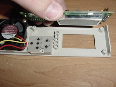
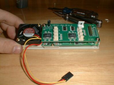
Taking the Digi-Doc apart is a pretty easy process. The only thing stopping you from replacing the LED's is 6 screws (4 typical screws & 2 screws/nuts similar to motherboard mounts). The first thing you need to do is pop out the main Digi-Doc controller from the drive tray it is connected too (metal frame behind the DD5 face plate). Once that is out, it is time to start unscrewing it and pulling it apart.
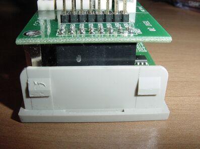
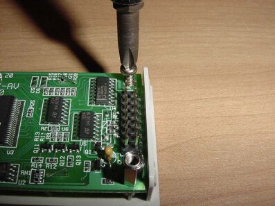
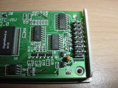
When you have the Digi-Doc 5 face plate sitting in front of you, turn it upside down so the LCD side is down and the PCB side is what you are looking at. Once you have done that, locate the top 2 screws. Once you have located these 2 screws, go ahead and unscrew them all the way out.
 Digi-Doc Upside Down (PCB Side) |
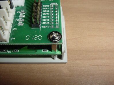 Top Screw #1 |
 Top Screw #2 |
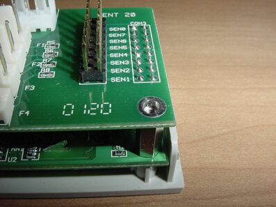 Top Screw #1 Unscrewed |
 Top Screw #2 Unscrewed |
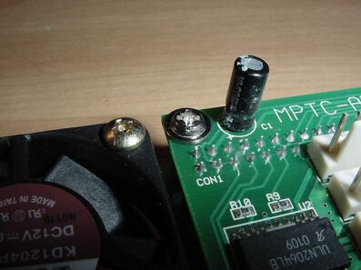
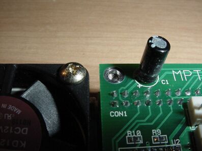
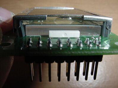
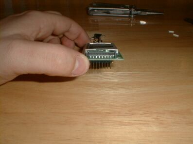
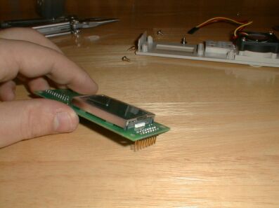
Once you have unscrewed the top 2 screws, it is time to lift the top PCB of the Digi-Doc off. To do this, all you need to do is pull up slowly in a side to side motion, on all sides of that top PCB. There are 2 connector junctions (1 20 Pin Junction & 1 16 Pin Junction) that are holding this top PCB on. Locate these 2 junctions and pull up easily at each junction.
 16 Pin Junction |
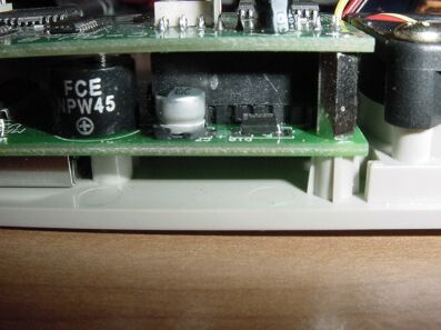 20 Pin Junction |
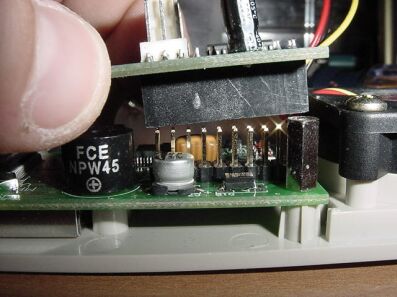 Pulling Up on 20 Pin Junction |
 Pulling Up on 16 Pin Junction |

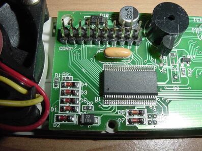
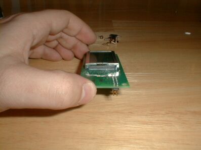
Top PCB Pulled Off
Showing bottom PCB still connected
to Digi-Doc Face Plate
Taking the last or bottom PCB off of the Digi-Doc 5 face plate is easier then removing the first face plate. Locate the 4 screws that stand in your way of completing the final removal part of the Digi-Doc 5. Once you have located the 4 screws (2 Philips Head (+) screws & 2 Motherboard mounting type screws), go ahead and remove them. You will need a pair of pliers to remove the 2 Motherboard mounting type screws and a Philips Head (+) screw driver to remove the other 2 screws.
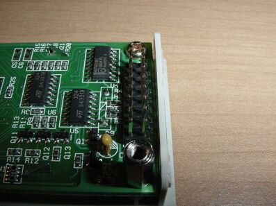 1 Philips Head (+) Screw & 1 Motherboard Mounting Type Screw |
 1 Philips Head (+) Screw & 1 Motherboard Mounting Type Screw |
 Remove Philips Head (+) Screw |
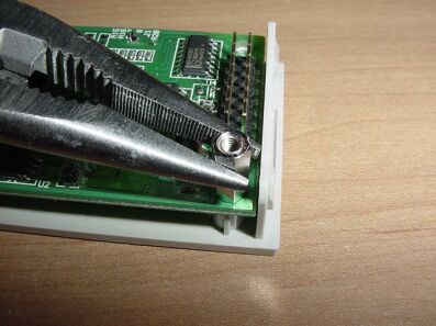 Remove Motherboard Mounting Type Screw |
 Both Screws Removed Side #1 |
 Both Screws Removed Side #2 |
Once all 4 of the screws are removed. All you need to do is lift up on the PCB and the entire unit will come right off.
Remove PCB From Digi-Doc Face Plate
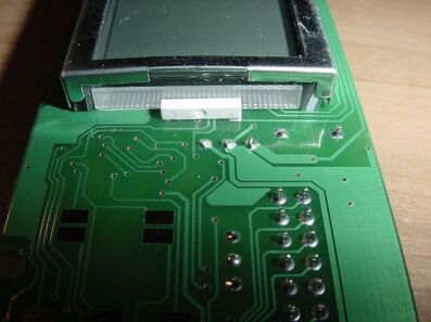
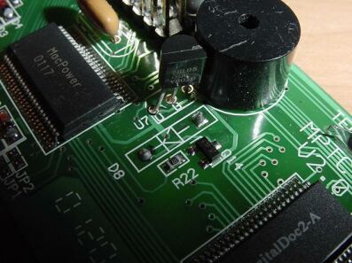
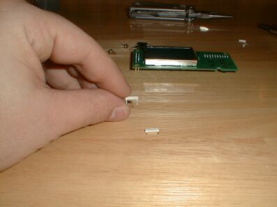
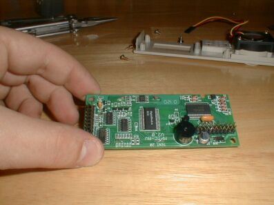
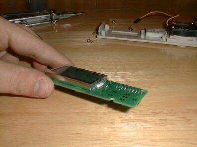
Once the bottom PCB is lifted off of the face plate, you can go ahead and lay it out in front of you. Look it over and locate the 2 rectangular LED's at either side of the LCD itself. The LED's are small white rectangles that are about 9MM in length. Once you have located them, turn it back over and look for the 4 solder points for these 2 LED's. Once you have located them go ahead and plug in the soldering iron and prepare for some hot fun.
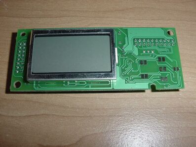 LCD & PCB Top View |
 LED #1 |
 LED #2 |
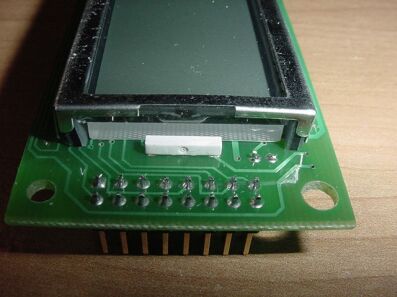
Close Up of LED
 LED Solder Points #1 |
 LED Solder Points #2 |
Removing the LED's
Once you have located everything and know where the 4 solder points that you are going to heat up so you can remove the LED's, it is time to go ahead and start removing them. I used the pliers once again to assist with the removal. I took the pliers and got a good grip of the LED. Then I started to apply the heat from the soldering iron to to one solder point at a time. I would apply the heat to the point and then with the pliers start pulling very lightly on the LED. Once the LED slipped out a little bit, I would go ahead and do the same thing on the 2nd solder point of the LED. I did this a couple of times until the LED came all of the way out. Once one LED was removed, I went ahead and started the same procedure on the 2nd LED.
Note: Try not to apply the soldering iron to a solder point for to long. The heat from the soldering iron has been known to destroy LED's and LCD's. Once I hit a solder point with some heat, I like to wait about 15 seconds before applying heat to the other solder point. This is just as a safety precaution and allows the area to somewhat cool before applying more heat.
I tend to go ahead and touch the areas I am applying the heat to, just to make sure the surrounding area isn't getting to hot and possibly causing damage to the other components. You don't want to destroy your LCD at this time since your warranty is now in the trash.
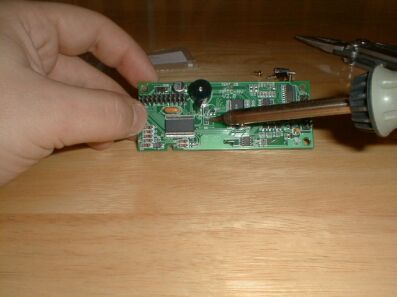 Applying Heat to a Solder Point |
 LED #1 Removed |
 LED #2 Removed |
Once you have the LED's removed, all you do is put them in reverse of the way you removed them. Here is where you will definitely not want to use a lot of heat when doing this especially if you are applying pressure to the LED's with your fingers. You can feel the heat build up. Once you start feeling the heat, it is time to remove the soldering iron and allow the connection to cool down. Make sure you attach the LED's with the clear part, where the anode and cathode are visible, towards the LCD.
 LED to be Installed |
 LED's Installed Solder Points |
 LED #1 Installed |
 LED #2 Installed |
Once the LED's are soldered in, you can go ahead and screw the PCB's back to the Digi-Doc Face Plate. The bottom PCB that contains the LCD is the one you want to make sure of that you have a nice tight screw. This allows the face of the LCD to be pressed hard into the face plate. This will ensure that your LCD numbers and letters are clear and bright.
Digi-Doc 5 Put Back Together
Back to Guides